Architecture
Learn about Designer architecture
Introduction
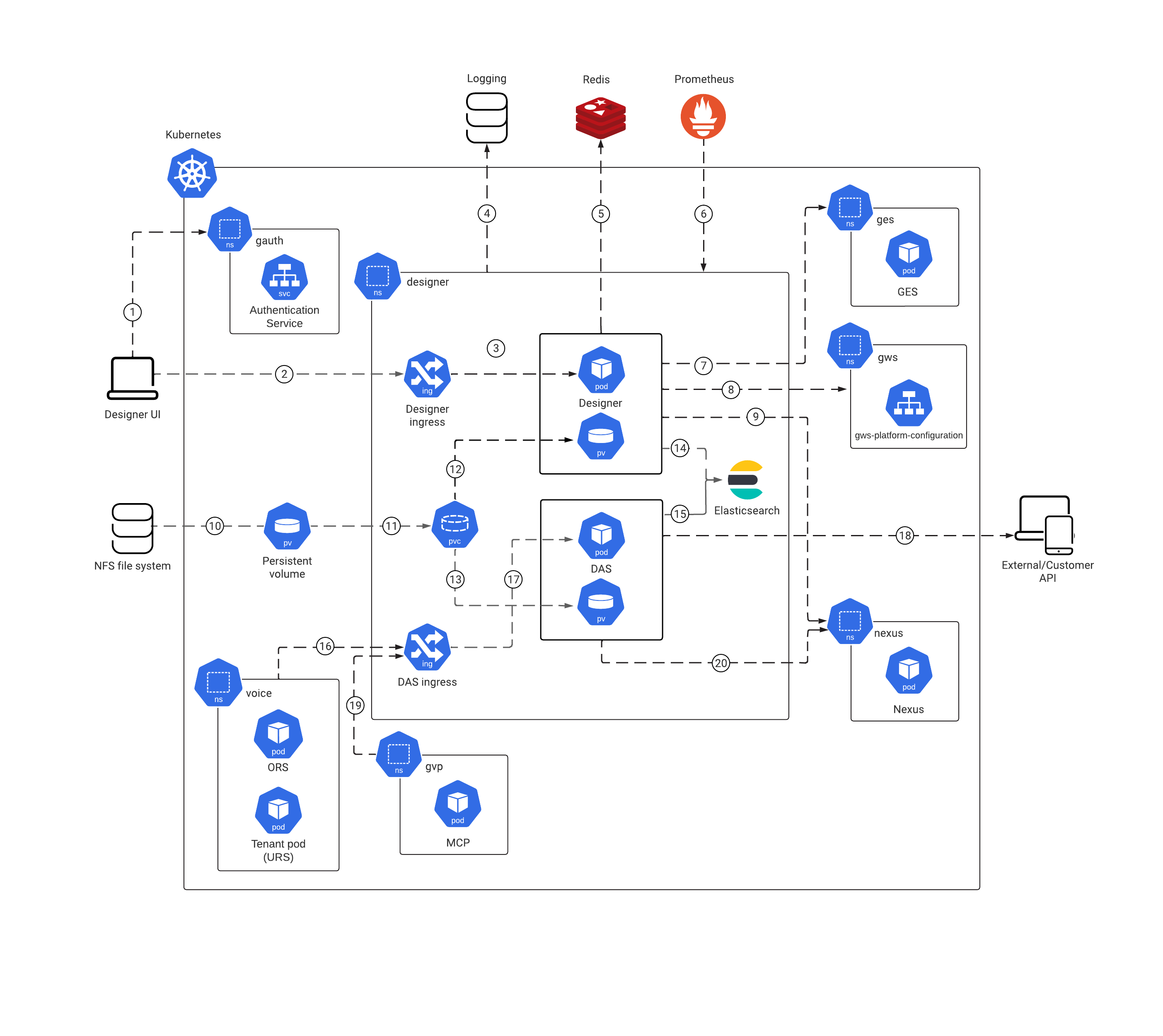
The architecture diagram in this topic illustrates a sample deployment of Designer and DAS.
For more information on the Genesys Multicloud CX private edition architecture, refer to the Architecture topic in the Setting up Genesys Multicloud CX private edition document.
For information about the overall architecture of Genesys Multicloud CX private edition, see the high-level Architecture page.
See also High availability and disaster recovery for information about high availability/disaster recovery architecture.
Architecture diagram — Connections
The numbers on the connection lines refer to the connection numbers in the table that follows the diagram. The direction of the arrows indicates where the connection is initiated (the source) and where an initiated connection connects to (the destination), from the point of view of Designer as a service in the network.
Connections table
The connection numbers refer to the numbers on the connection lines in the diagram. The Source, Destination, and Connection Classification columns in the table relate to the direction of the arrows in the Connections diagram above: The source is where the connection is initiated, and the destination is where an initiated connection connects to, from the point of view of Designer as a service in the network. Egress means the Designer service is the source, and Ingress means the Designer service is the destination. Intra-cluster means the connection is between services in the cluster.
| Connection | Source | Destination | Protocol | Port | Classification | Data that travels on this connection |
|---|---|---|---|---|---|---|
| 1 | Customer browser | Genesys Authentication | HTTPS | 8095 | Intra-cluster | Designer queries the Genesys Authentication Service to validate the user’s identity. |
| 2 | Designer ingress | HTTP | 443 | Ingress | Web browser used to access the Designer UI. | |
| 3 | Designer ingress | Designer | HTTP | 8888 | Egress | Incoming web traffic from the UI. |
| 4 | Designer | Logging | HTTP | Egress | Centralized logging. | |
| 5 | Designer | Redis | HTTP | 6380 | Egress | Resource index caching and multi-user collaboration locks on Designer resources. |
| 6 | Prometheus | Designer | HTTP | 8888 | Ingress | Metrics for monitoring and alerting with Prometheus. |
| 7 | Designer | Genesys Engagement Service | HTTP | 80 | Publish callback services. | |
| 8 | Designer | Genesys Web Services and Applications | HTTP | 80 | Authentication of Designer and configuration data access. | |
| 9 | Designer replica set | Nexus | HTTP/HTTPS | 80 | Ingress | Fetch Designer Bot registry information. |
| 10 | Shared file system (NFS) | Persistent volume | NFS for workspace storage. | |||
| 11 | Persistent volume | Designer Persistent Volume Claim (PVC) | Data for workspace storage. | |||
| 12 | Designer Persistent Volume Claim (PVC) | Designer replica set persistent volume | Data for workspace storage. | |||
| 13 | Designer Persistent Volume Claim (PVC) | DAS replica set persistent volume | Data for workspace storage. | |||
| 14 | Designer | Elasticsearch | HTTP | 9205 | Egress | Query Designer Analytics data (Session Detail Records). |
| 15 | Designer Application Server | Elasticsearch | HTTP | 9205 | Egress | Store Designer Analytics data (Session Detail Records). |
| 16 | Voice Microservices | DAS ingress | HTTP | 80 | Ingress | Fetch Designer application pages (VXML, SCXML), JSON files, and so on. |
| 17 | DAS ingress | Designer Application Server | HTTP | 8080 | Ingress | HTTP traffic from DAS ingress. |
| 18 | External/Customer | Designer Application Server | HTTPS | 443 | Egress | External customer API requests. |
| 19 | Genesys Voice Platform | DAS ingress | HTTP | 80 | Ingress | Fetch Designer audio resources. |
| 20 | Designer Application Server | Nexus | HTTP/HTTPS | 80 | Ingress | Fetch GES APIs for callback processing. |

